Brief: ScintPack software, in conjunction with either its companion data conversion / acquisition hardware Model SP-100, or an IN/US Systems B-RAM radioactivity flow monitor, can be used to monitor the differential pressure of the IN/US Systems' TRI-SORBER tritiation manifold, and can provide the operator with useful information and documentation concerning the tritium labeling process.
ScintPack can process a 'differential data type', necessary to properly convert and report the TRI-SORBER's differential pressure into a more useful form. With differential processing, a real time quantitative determination, of the tritium reaction, in units specified by the user is possible. Further, the operator can determine at what time the expected amount of tritium has reacted, and thus avoid sample damage or excessive labeling of unwanted bonding sites. Additional applications and uses of ScintPack with the TRI-SORBER include:
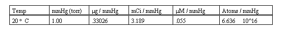
The following table lists the conversion factors for each 1 cc of reaction volume, per 1 mmHg. These values must be multiplied by the total reaction volume in cc, and by the ADC conversion gain, all to be explained and determined next.
The basic units of differential pressure measurement of the TRI-SORBER system are in mmHg. The output voltage range of the TRI-SORBER's differential pressure module is specified at either 1.00 volt = 1000 mmHg or 10.00 volt = 1000mmHg, depending on the model TRI-SORBER used.
The ADCs of both the B-RAM and the SP-100 convert a full scale input signal to a digital value of 10,000. If a 1.00 volt full scale input signal represents a pressure of 1000 mmHg and converts to a digital value of 10,000 then mmHg are represented directly by multiplying 10,000 by .1. Likewise, if a 10.00 volt full scale input signal represents a pressure of 1000 mmHg and converts to digital value of 10,000 then mmHg are again represented directly by multiplying 10,000 by .1. The full scale input range is a hardware configuration selected by a switch or jumper, on either the (B-RAM or the SP-100.
The reaction volume of the TRI-SORBER manifold is specified as being 2.47 cc plus a .1 cc volume in the tubing which connects the sample isolation valve with the reaction vessel, giving a total fixed reaction volume of 2.57 cc. This value must be added to the head space volume in the reaction vessel in order to obtain the total reaction volume.
In the case where the reaction vessel is held at a temperature different than ambient, a separate calculation would be necessary to correct the affected portion of the gas volume of the reaction vessel for temperature. As there seems to be no means of dealing directly with a temperature gradient, it may be sufficient to consider the tube connecting the isolation valve with the reaction vessel as being half ambient and half at the reaction vessel temperature, and correct the masses in the contributing volumes accordingly. In any case, accurate results can only be obtained if the temperature of the apparatus and the reaction vessel remains constant during the reaction time.
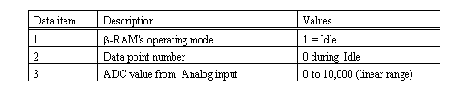
The Setup will automatically download and initialize the B-RAM with the acquisition parameters. It is not necessary to set Run Length because ScintPack will capture the data while B-RAM is in the Idle mode. The B-RAM does not need to be placed in the Run Mode for this application.
Note: B-RAM's serial Host Port produces a data frame each second. The data elements within the data frame are separated by the delimiter character, (comma). The order and significance of the data items is as follows:
A 5 ml reaction vessel is loaded with 3 ml of liquid sample. We add the remaining gas volume of 2 cc to the fixed reaction volume of the TRI-SORBER, resulting in a total reaction volume of 4.57 cc.
A factor from the table above, determined by the data units desired (mmHg (torr), g, mCi, (M etc.) is multiplied by the total reaction volume to determine the quanitation factor (QF) per mmHg.
The ADC conversion gain is multiplied by the QF, the product is then entered as the User Factor on the Method Generator program screen of ScintPack.
The Tritium gas is admitted to the manifold, the valves are properly sequenced to expose the gas to the sample, the data acquisition session is begun and the pressure is monitored and recorded for 120 minutes.
The graph below depicts the differential pressure curve during the course of the reaction. The vertical scale units are automatically reported in mCi owing to the factor which converts pressure to mCi.
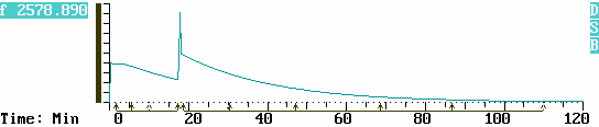
More tritium was added to the manifold at 17:30 min. The sample isolation valve was closed, more tritium gas was driven into the manifold, and the isolation valve was reopened. The effect of the resulting pressure disturbance and spike is omitted from the calculations by tagging around it with the Cursor.
As the reaction progresses, the user can tag time regions with the Cursor and obtain an immediate result for each region, thus the reaction rate is quantitatively monitored in real time. By viewing the on screen Result Table, all time regions up to and including the latest region can be examined.
With a real time visual indication of the reaction's progress the user can determine, whether or not the reaction should be allowed to continue. As the reaction is monitored, annotation can be added in the Comment Area, thereby preserving a record of observations.
The time values noted in the table below, correspond to Regions of Interest (ROIs) which the operator tagged with the Cursor in order to monitor the reaction as time passed. Each ROI reports the difference between the beginning and end of the region in mCi. The minus sign indicates that mCi are leaving the reaction volume (mass, and therefore pressure is decreasing) and are being incorporated in the liquid sample.
The column labeled Cumulative Differential is a running sub total of the differentials of the individual ROIs, and too is reported in mCi.
The column headings Name and Peak Time have significance in various other analytical methods, such as in chromatography, but have no particular meaning in his application.---------------------------------------------------------------------------- Trace 1 DiffPres Differential Time Series Data Factors are Applied! Baseline1 0.00 Baseline2 0.00 ConvFact UserFact 1.457 ---------------------------------------------------------------------------- Reg Name Start Stop Peak Diff Cumulative No. Time Time Time mCurie Differential ---------------------------------------------------------------------------- 1 __________ 1:35 5:40 1:36 -74.307 -74.307 2 __________ 5:40 10:11 5:40 -150.071 -224.378 3 __________ 10:11 17:12 10:11 -198.152 -422.530 4 __________ 18:34 30:20 18:34 -493.923 -916.453 5 __________ 30:20 47:06 30:20 -384.648 -1301.101 6 __________ 47:06 68:36 47:08 -217.093 -1518.194 7 __________ 68:36 86:43 68:36 -74.307 -1592.501 8 __________ 86:43 110:02 86:43 -32.054 -1624.555 ----------------------------------------------------------------------------
The Results Table can be pre-viewed on screen while data acquisition is in progress, and can be previewed or printed when the data acquisition session is over. Printout of data previously acquired can be made anytime as long as the data has not been removed from its assigned directory.
One may readily recognize that the profile of pressure drop is characteristic of an exponential decay function. Indeed many physical, chemical and biological processes follow the natural decay law, and this kind of gas reaction is no exception.
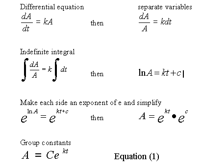
The equations needed to model an exponential decay characteristic are developed as follows.
A data file named TRISORB1 is included in the distribution copy of ScintPack. The data is collected from the differential pressure module of an IN/US TRI-SORBER tritium manifold, and represents an actual tritium labeling session. The file contains two traces of the differential pressure, each having a different factor thereby producing results in both mCi and Mol units
In the following discussion we will determine the reaction rate, from a portion of the pressure decay curve, beginning at 18:00 minutes.
If you have ScintPack, are familiar with its use, and want to follow along with this analysis, then start the program and select Evaluate Data from the Main Menu. Then select the TRISORB1.R01 filename for evaluation. Note that the Cursor reports time as minutes and seconds while the calculations below use minutes in decimal format.
Expand the Horizontal scale to view 15 to 25 minutes.Move the Cursor to 18:00, and observe the Cursor data at 1280.7 mCi of gas present in the reaction volume. The 18:00 min. mark is considered time t = 0 , for this segment of the curve.
Substituting 1280 for A, into Equation (1) and solving for C at t = 0, gives C = 1280, so now
Scroll forward horizontally using Alt+F9 to view 30 to 40 minutes.
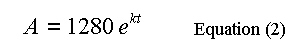
Move the Cursor to 34:14, and observe the Cursor data at 639.6 mCi of gas present in the reaction volume, just about half of the amount at 18:00 min. Any point can be used in this step, but half (life) is intuitive, commonly encountered and easy to deal with.
Substituting 640 for A, in Equation (2) and solving for k at t = 16.23 min. (34:14 min. - 18:00 min.), we have:
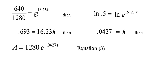
The values read from the Cursor and the calculated value of k, are rounded off so a small error will creep into the calculations as we proceed to use Equation (3). From Equation (3) we can now solve for A at any time t, then subtract that result from 1280 and find the quantity of gas that has reacted up to time t.
At the end of every 16.23 minute interval, the amount of gas remaining in the reaction volume should be half of what it was at the beginning of the that interval.
Test for a single reaction rate constant. See if every 16.23 minutes the amount of gas remaining in the reaction volume is reduced by one half.
Scroll forward to view 45 to 55 minutes.Move the Cursor to 50:27, (equals 18 min. + 2 * 16.23 min. or two half lives) and observe the Cursor data at 323.4 mCi of gas present in the reaction volume, about half of the 34:14 min. value.
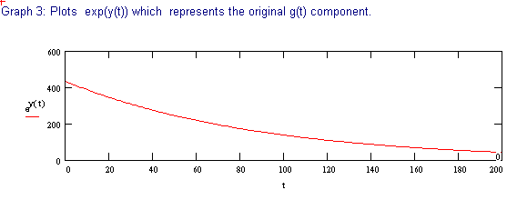
This is very close to the expected value of 320 mCi, so it appears that in this case, a single time constant fully describes the reaction. This is not to imply that a single bonding site is involved in the reaction, but rather implies that there are not several bonding sites with widely differing reaction constants being labeled.
Next, we can determine at what point in time a given amount of gas will have reacted with the sample. The user can determine the reaction rate early on, find the constants in Equation (3), then calculate forward and know about when a predetermined amount of tritium will have reacted with the sample.
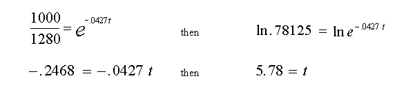
Example: At what time will 280 mCi have reacted with the sample.First, find the remaining mCi in the reaction volume when 280 mCi have reacted, (equals 1280 minus 280 or 1000 mCi) then substitute for A in Equation (3) and solve for t.
Using the ASCII file function, data from ScintPack can be transferred to a variety of other programs, such as spread-sheets and math intensive applications, where more complex data reduction and processing can be done.
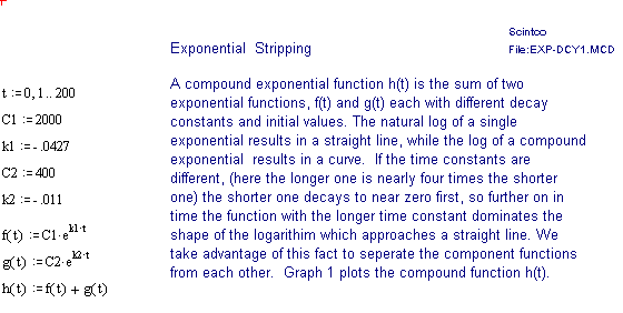
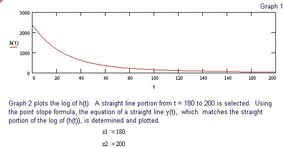
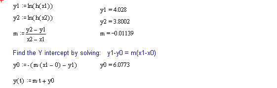
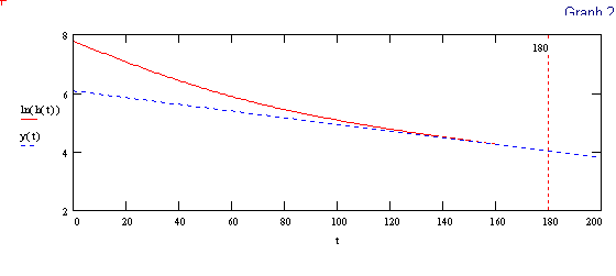
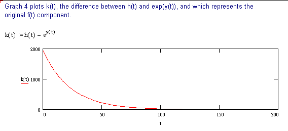
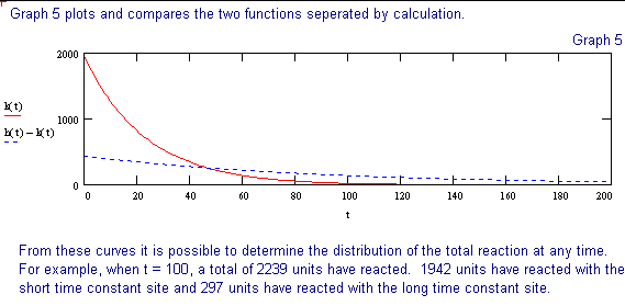
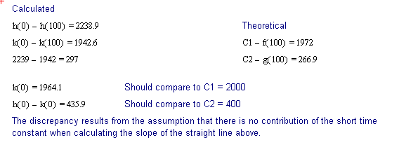
The following discussion outlines a procedure for separating two, single time constant exponential decay functions, from a function containing two time constants. These conditions could be encountered when labeling compounds with tritium. The primary requirement for successful separation is that the two decay constants differ significantly.
The 2 page attachment was created with MathSoft's Mathcad ver 4.0. Initial values and decay constants are selected in order to illustrate the method of exponential stripping and do not derive from actual data.
Comments and explanations are depicted in bold typeface, while the actual variables, assignments, formulae and expressions are depicted in normal typeface.